How to run and configure Firewall as a service and VPN as a service on CloudFerro Cloud
This guide provides a sample process for configuring VPN as a service. It should not be considered the only way to configure this solution.
Note
The solution presented in this article is only suitable for low network traffic use cases involving achievable bandwidth of approximately 200 megabits per second. This is sufficient for managing your servers via the Command Line Interface (CLI), but not suitable for high-traffic use cases involving gigabits per second.
What We Are Going To Cover
Prerequisites
No. 1 Account
You need a CloudFerro Cloud hosting account with access to the Horizon interface: https://horizon.cloudferro.com/auth/login/?next=/.
No. 2 Create and access a VM in the cloud
The following articles explains how to create a new Linux VM using Horizon and access with SSH:
How to create a Linux VM and access it from Windows desktop on CloudFerro Cloud
How to create a Linux VM and access it from Linux command line on CloudFerro Cloud
To access it via SSH, see How to Add or Remove Floating IP’s to your VM on CloudFerro Cloud
If you forgot to enter a key pair during the installation, see How to add SSH key from Horizon web console on CloudFerro Cloud
No. 3 Graphical user interface for a VM
Click here for instructions on how to install a GUI on an Ubuntu 20.04 VM:
How to Use GUI in Linux VM on CloudFerro Cloud and access it From Local Linux Computer.
Depending on your local operating system, the installation of X2GO may vary in difficulty. If you are not using a Debian/Ubuntu-based Linux, consider creating a local VM with Ubuntu 22.04 and connecting to Test_Ubuntu from there.
Create FWAAS Infrastructure
To start VPN as a service, you first need to configure and start Firewall as a Service (FWAAS).
Creating a network called Gateway
Log in to the OpenStack dashboard and go to Network → Networks and click on Create Network button.
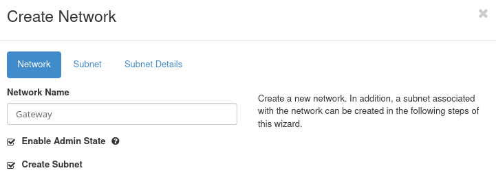
Set the Network Name to Gateway and go to the Subnet tab.
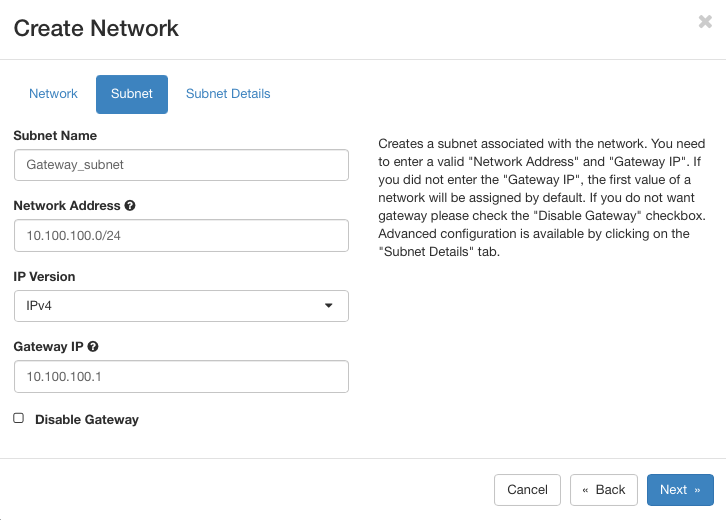
Set the Subnet Name to Gateway_subnet. Use the following settings:
Network address: 10.100.100.0/24
Gateway IP: 10.100.100.1
Click on Next to get to Subnet Details screen. There, ensure Enable DHCP is checked, leave other fields blank and click on Create.
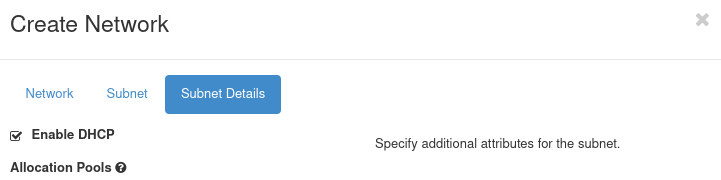
The Gateway network is created.
Creating a network called Internal
Repeat the previous steps with different details:
Network Name: Internal
Subnet Name: Internal_subnet
Network Address: 10.200.200.0/24
Internal IP: 10.200.200.1
The result that these two networks are visible in Network → Networks menu:
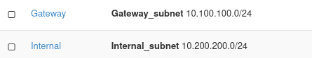
Note
Depending on the state of the other networks in the system, it may not always be possible to achieve the same values as in this article. For instance, instead as 10.200.200.1 as above, you may have 10.200.200.2 or some other value. Note them down and replace accordingly while working through the article.
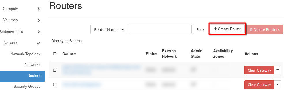
Create a router
Click the Create Router button.
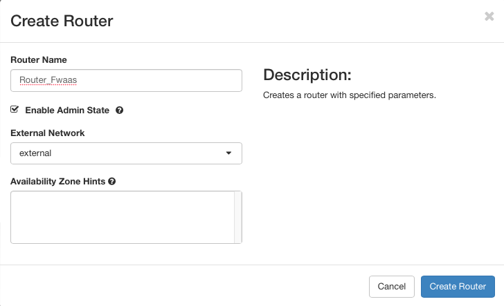
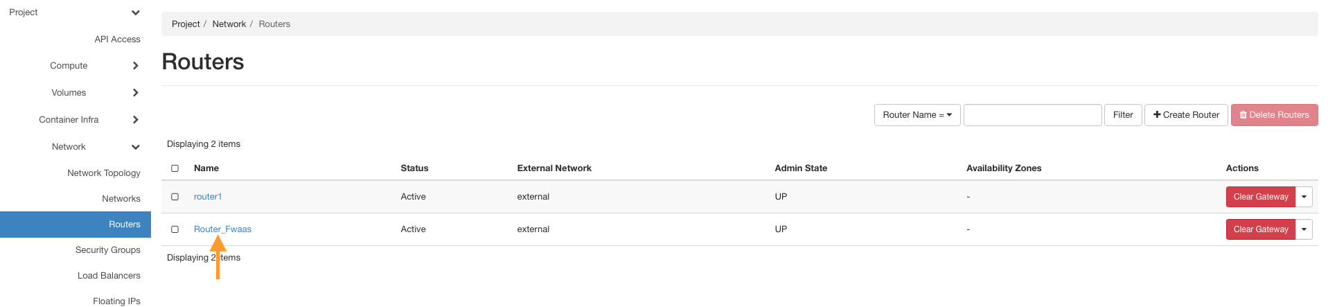
Name the router (e.g., Router_Fwaas). Select the external network in the External Network tab and click Create Router.
Click the name of your new router.
Go to the Interfaces tab and click Add Interface.
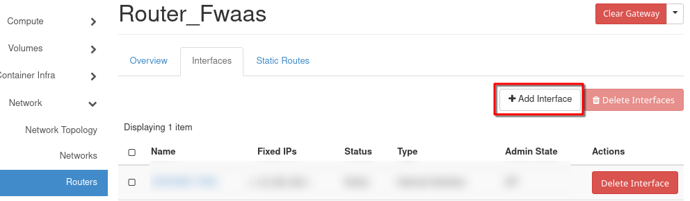
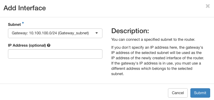
From the Subnet dropdown, select Gateway_subnet and click Submit.
To view the network layout, go to Network → Network Topology.
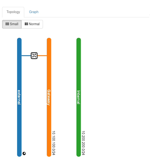
Note
The above image shows a very simplified topology of the network; in real life situation, and especially if you are creating Kubernetes clusters and such, this graph would be much more complicated.
We have created two networks and a corresponding router with ports, therefore, we are now able to create a virtual machine on which OPNsense software will run.
Creating and configuring the VM with OPNsense
Prerequisite No. 2 shows how to create a new virtual machine under OpenStack. In this article, we will be using much the same procedure and the only unusual option we will use is adding a script to customize the OPNsense IP with the VM’s IP.
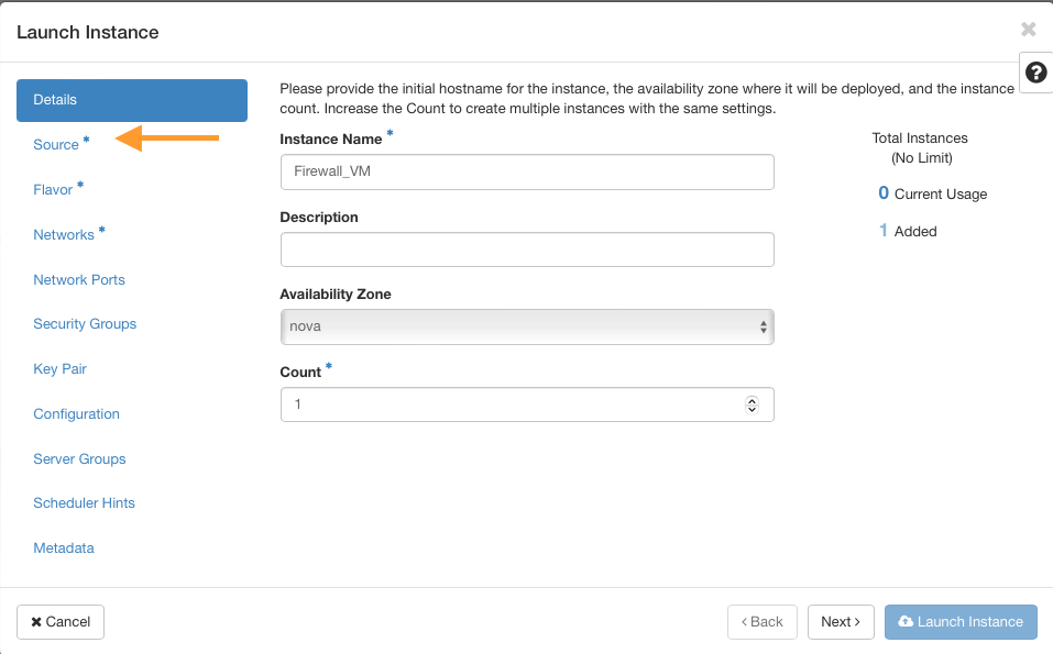
Navigate to Compute → Instances and click Launch Instance.
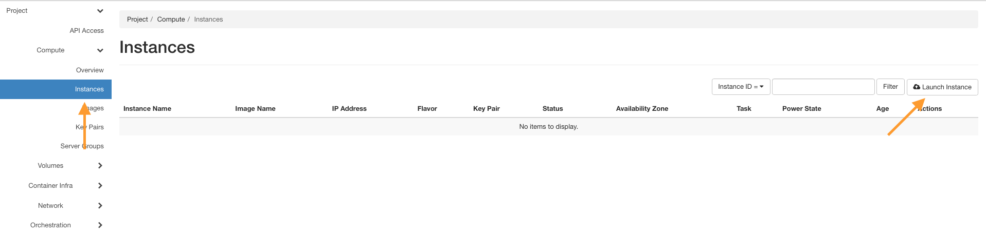
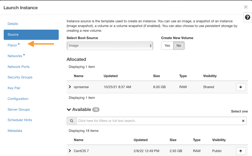
Enter a name, e.g., Firewall_VM, and go to the Source tab.
Choose the opnsense image and move it to the allocated side. Then go to the Flavor tab.
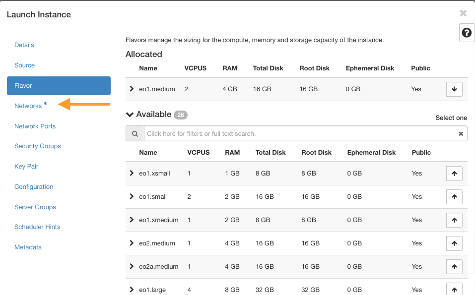
Use appropriate flavors for OPNsense
Minimum requirements:
CPU: 1 Core
RAM: 2 GB
Disk: 8 GB SSD
Suggested flavor: eo1.xmedium
Optimal setup:
CPU: 2 Core
RAM: 4 GB
Disk: 16 GB SSD
Suggested flavor: eo1.medium
Insert networks
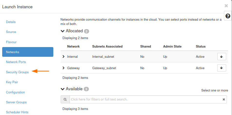
Go to the Networks tab.
Add the created networks in this order:
Internal network
Gateway network
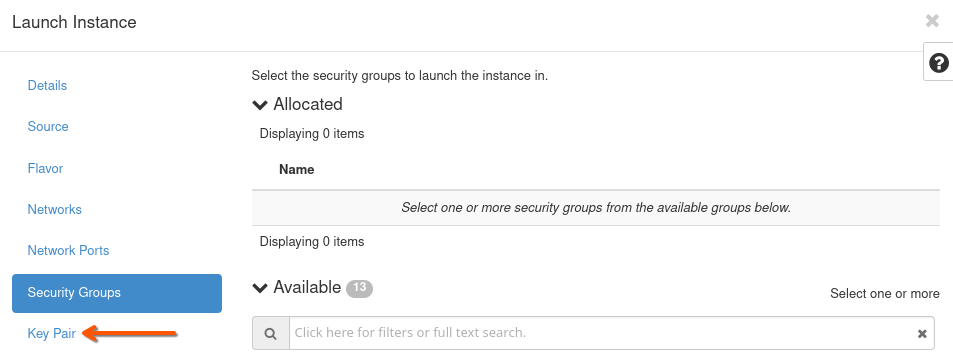
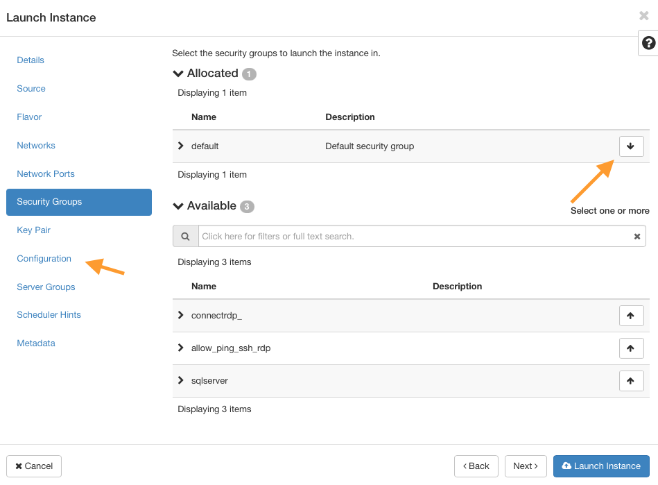
Clear security groups
Navigate to Security Groups and remove all attached security groups by clicking the arrow on the right of each row.
Note
We remove all security groups from the VM because firewall filtering will be handled entirely by the OPNsense server. Make sure Port Security is disabled on all ports connected to the firewall VM, or traffic may be blocked by OpenStack’s default filters.
Key Pair
Define or use an existing SSH key pair to access the VM later. See Prerequisite No. 2 for guidance.
Note
It is the OPNsense image that we are here dealing with, so the usual rules for opening an SSH connection for Linux-based VMs do not apply here. If you need to use SSH on OPNsense server, you will have to alter its parameters via OPNsense GUI first.
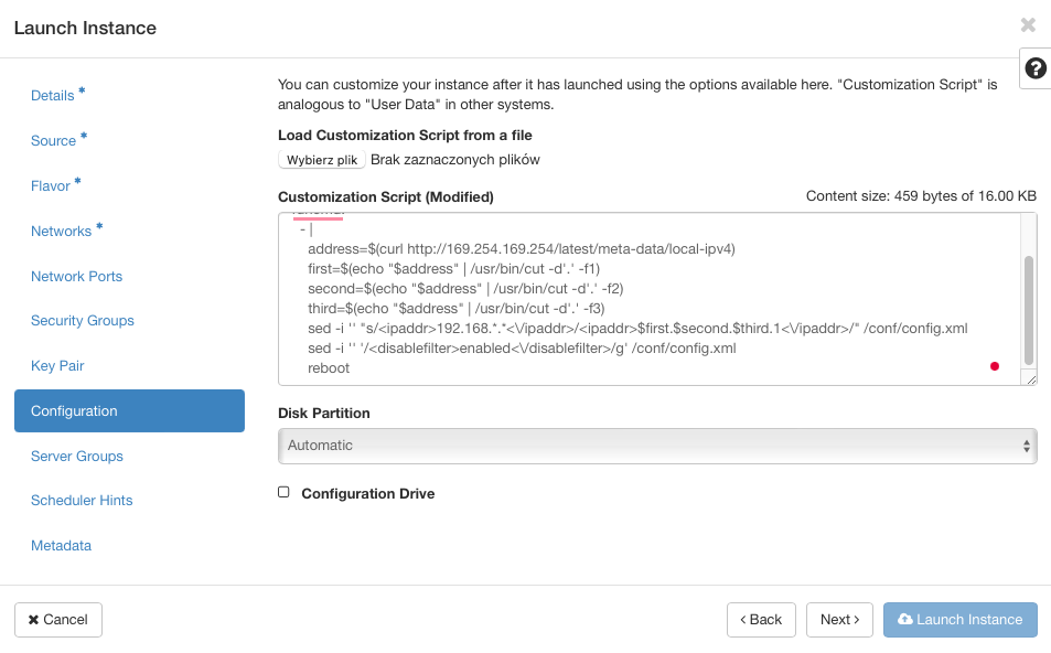
Customize the VM using a script
Open the Configuration tab.
Paste the following script into the Customization Script box:
# This script replaces the default OPNsense IP with the VM's IP
runcmd:
  - |
    address=$(curl -s http://169.254.169.254/latest/meta-data/local-ipv4)
    first=$(echo "$address" | cut -d'.' -f1)
    second=$(echo "$address" | cut -d'.' -f2)
    third=$(echo "$address" | cut -d'.' -f3)
    sed -i "s|<ipaddr>192\.168\.[0-9]\+\.[0-9]\+</ipaddr>|<ipaddr>$first.$second.$third.1</ipaddr>|" /conf/config.xml
    sed -i "/<disablefilter>enabled<\/disablefilter>/d" /conf/config.xml
    reboot
Launch the VM
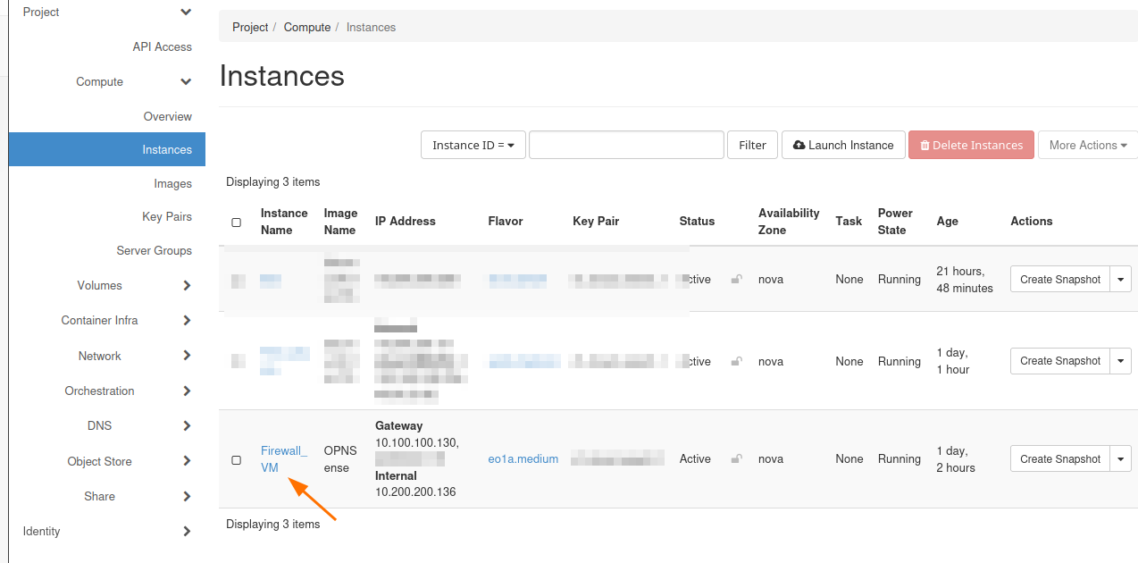
Click Launch Instance and wait for the VM to spawn.
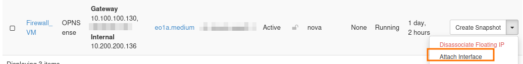
If everything is in order, you should see at least two IP addresses for Firewall_FM, like this:
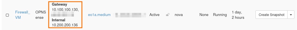
If one of these ports is missing, add them with option Attach interface from the action menu on the right side.
Note
Once again, while working through the article, use IP addresses as shown in command Compute -> Instances instead of those you see in the screenshots above.
Add port for Interfaces
Once the VM is created, click on its name in the Instances tab.
Go to the Interfaces tab and click on Edit Port on each port.
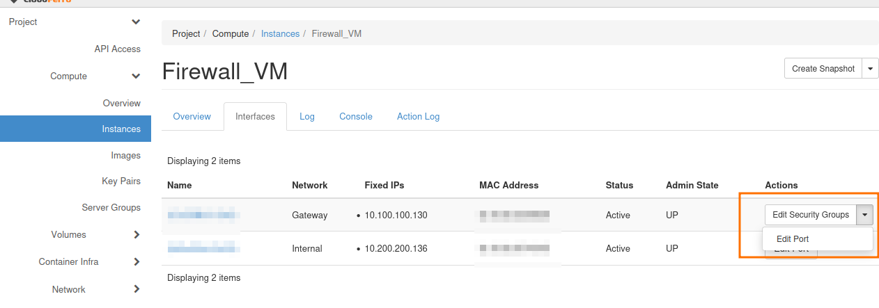
Disable Port Security and click on Update.
Allocate Floating IP
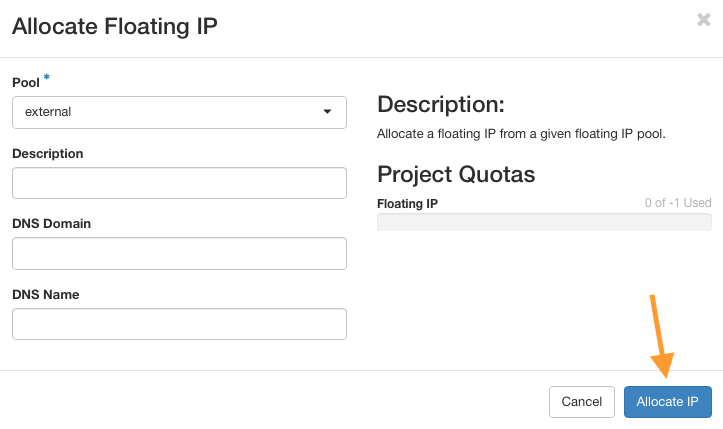
Go to Network → Floating IPs and click on button Allocate IP to Project.
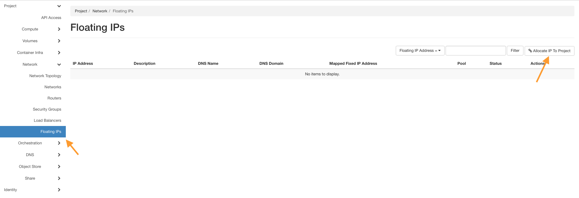
Click on button Allocate IP without entering anything else.
Click on Associate next to the new Floating IP and attach it to the Firewall_VM port connected to the Gateway network (10.100.100.130 in our case).
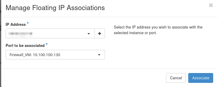
Using this Gateway network interface will enable the OPNsense server to access the Internet.
Using dashboard to set up the OPNsense server
Speaking in more technical terms, the LAN address for Firewall_VM instance is called vtnet0 and its value should be the address of Internal’s network Gateway IP, which is 10.200.200.1. You can check it by clicking on Compute –> Instances –> Firewall_VM –> Console to open console in Horizon. To enter, use the following credentials:
User: root
Password: opnsense
and you should see a screen like this:
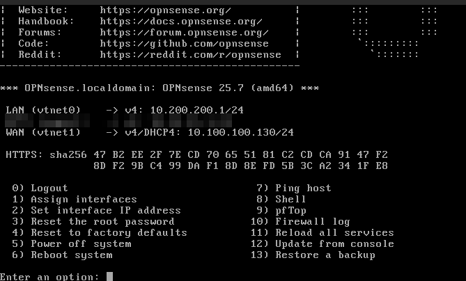
The Firewall_VM LAN address vtnet0 should be identical to that you see in Horizon (Network->Networks->Internal->Subnets->Gateway IP), that is, 10.200.200.1. If the LAN address is different, you will configure it in next steps.
Add or set up the existing interfaces
At the bottom of the screen, there is a prompt Enter an option so type 1 and press Enter on the keyboard.
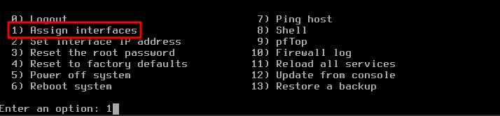
Entering 1 will execute command Assign interfaces as shown in the red rectangle in the image above. With this, we are going to set up the interfaces, which are called vtnet0 and vtnet1 on OpenVPN server.
After pressing Enter, a new question will appear:

Pressing Enter in this kind of interface will execute the option that is represented as a capital letter. Here it is N, so by pressing Enter you have effectively negated the option to configure LAGGS. Since that acronym stands for Link Aggregation Group Interface and we are not interested in that here, N means skipping it.
The next question is to set up VLANs now; again, press Enter to skip it. The screen changes to:
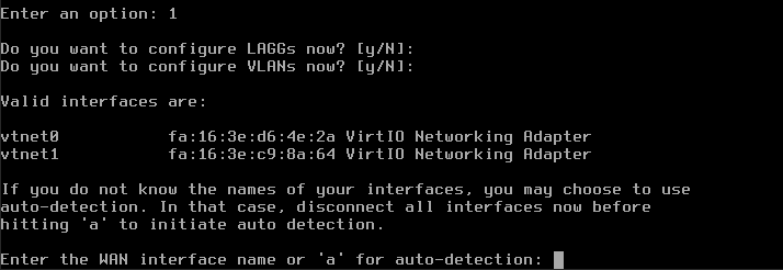
WAN stands for Wide Area Network and the corresponding interface is vtnet1 so enter that.
For question Enter the LAN interface name or ‘a’ for auto-detection NOTE… enter vtnet0.

The next question is Optional interface 1 – leave it blank and press Enter. Those steps are captured on the following picture:
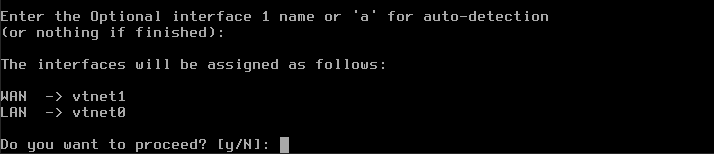
You will see prompt The interfaces will be assigned as follows: WAN -> vtnet1 LAN -> vtnet0 – nothing to do here, as it is correct. Next, y for Do you want to proceed? and click enter to save your changes.
Setting the address of vtnet0 manually
We are now back to the main menu for OpenVPN. We will set up the IP address for vtnet0 manually, by entering 2 for Enter an option:. That activates option Set interface IP address from the main menu.
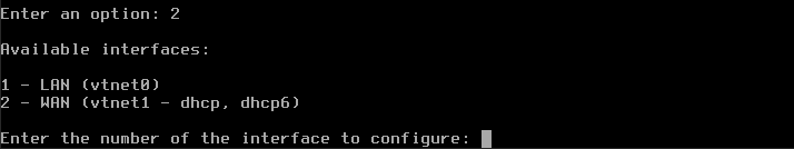
Enter 1 to set up LAN and you will see this question:
Configure IPv4 address LAN interface via DHCP
Press Enter for N and get another question:

Type your internal IP address, which in this case is 10.200.200.1.
Warning
Instead of 10.200.200.1 enter the actual value you got in option Compute -> Instances for the Internal network.
Then follows the question how many bits should be taken into account:
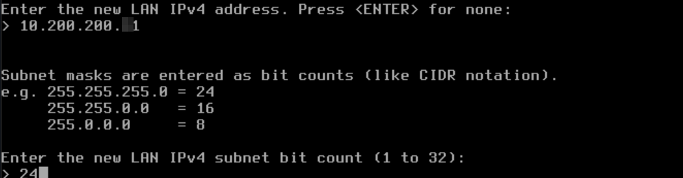
Enter 24 (CIDR notation: 255.255.255.0/24).
The result of all these entries is that the interfaces for LAN static IP address and WAN DHCP4 address are now configured.
Now another series of questions will follow, but keep on pressing Enter to confirm the default values. You will end up with the following screen, which will now contain correct values for LAN and WAN interfaces:
If you made a mistake in any of the steps, please repeat procedure from the beginning, starting from 1 for Enter an option: in the main menu.
The procedure of using web console from Horizon is finished.
Checking the console log
Now make sure that the changes are visible in the console logs. Since you are still in web console interface, click on back arrow of your browser and get to the submenu for Firewall_VM instance:
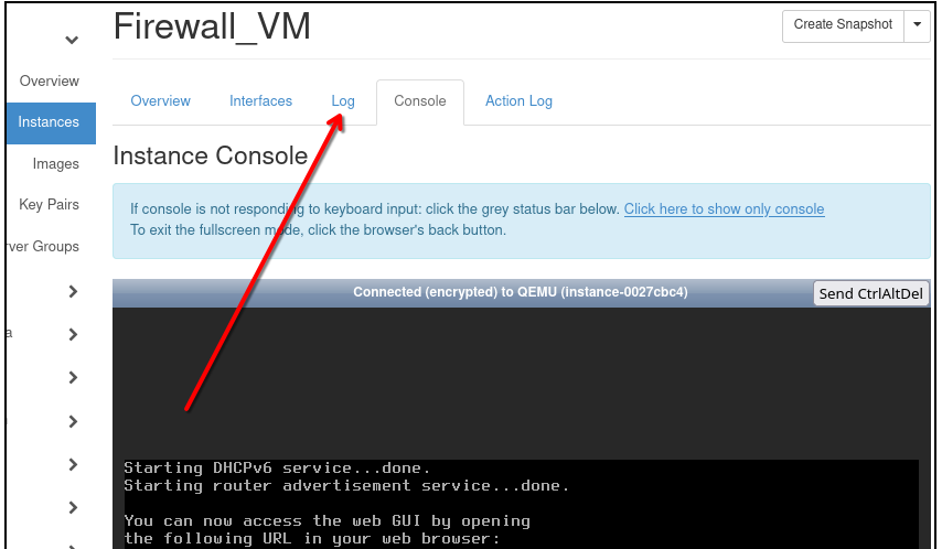
Click on Log as shown by the red arrow. The text in the log is shown up, and notice that there the LAN and WAN addresses are shown.
WAN address is probably empty (for now).
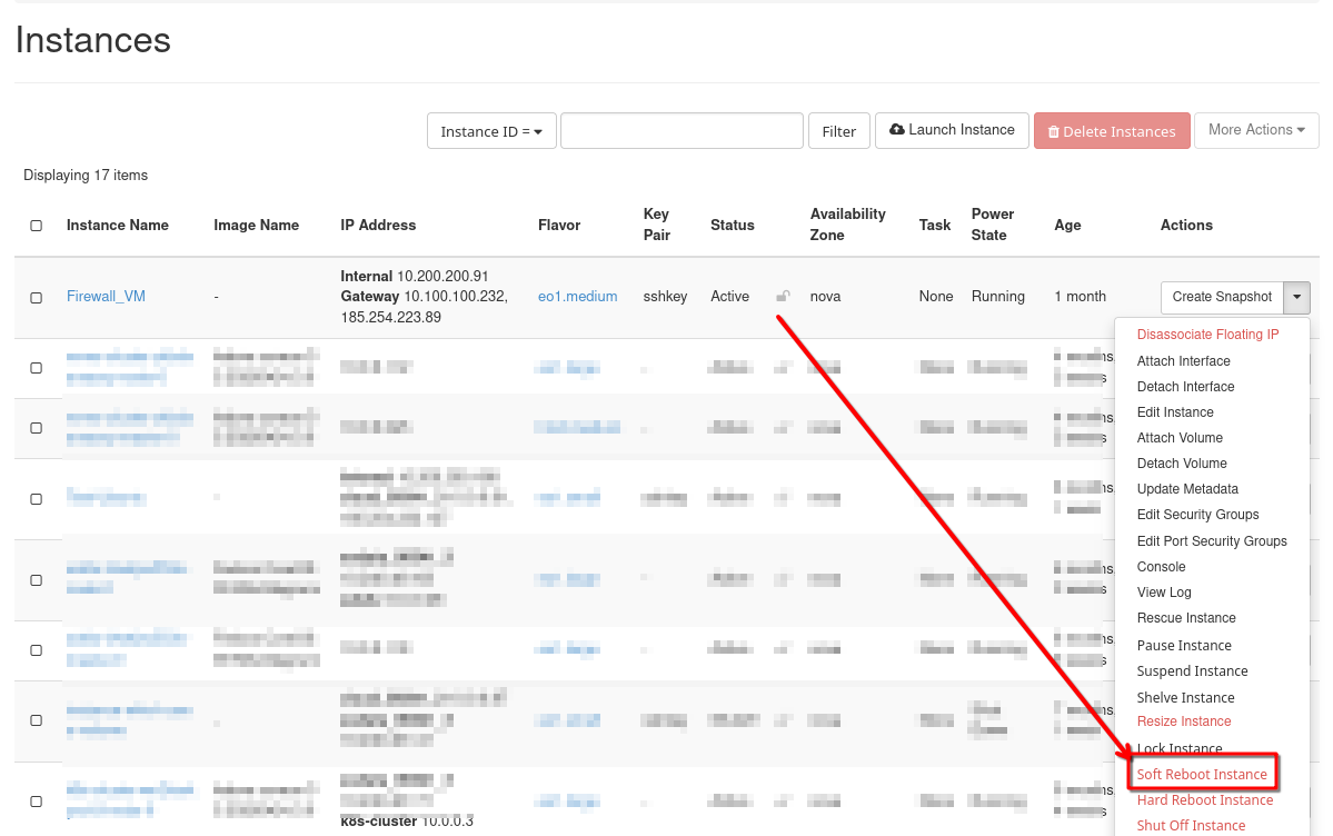
Refresh the VM
Now perform Soft Reboot Instance in order to refresh Log data:
Check the console log once again and verify that both addresses are now correctly filled in:
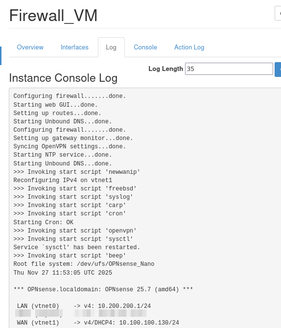
The instance that OpenVPN will run on, Firewall_VM, has now been prepared and the next step is to provide parameters to the OpenVPN server.
Use another VM in the same cloud to access Firewall_VM
Firewall_VM is running on FreeBSD and is optimized for fast running of opened connections. It has no special graphical instance of its own, so if we want to use a GUI to make the VPN work, we need to circumvent the problem in the following way:
Create another instance on OpenStack or use one that you already have. In this article, this auxiliary virtual machine will be called Test_Ubuntu. If you are creating it anew, use Ubuntu 20.04 or 22.04 for its image.
Next, add access to Internal network, 10.200.200.0/24, so that these two instances can share data. The net result will be that we enter commands through Test_Ubuntu and they are executed on Firewall_VM.
You must also have SSH access to that virtual machine. See Prerequisite No. 2.
Use local Linux/Windows machine to access OPNsense GUI
You can proceed if Test_Ubuntu has defined an
Internal IP address (in this article, it is 10.200.200.136) and a
Floating IP attached to it.
In your local terminal, use ssh protocol to connect to Test_Ubuntu by executing the following command:
ssh -L 8443:10.200.200.136:443 eouser@here_type_floating_IP_of_a_Test_Ubuntu
and click enter. If you want to include the “secure” part of the key pair, use the command like this:
ssh -i your_key.pem -L 8443:10.200.200.136:443 eouser@<floatingIP>
where you have to replace <floatingIP> with Floating IP of your Test_Ubuntu and click enter.

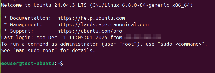
Once you connected, you should see a screen with eouser, which in your case should be eouser@Test_Ubuntu:~$ like this:
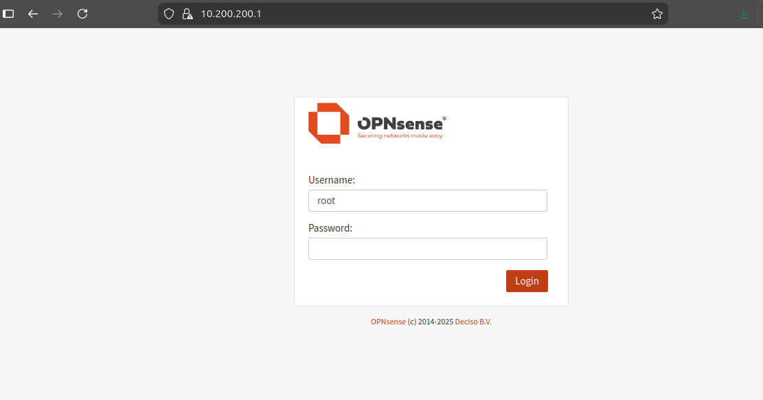
Open local web browser and type: https://localhost:8443
Note
The first time you run it, there will be a warning that the site you want to visit is unsecured. This is normal since there is no security certificate on the OPNSense server at this point. In Firefox, click Advanced… on the warning page and then click Accept the Risk and Continue. Other browsers will have their own ways of handling this situation.
The credentials to log in are:
Username: root
Password: opnsense
You will be presented with the wizard for the general setup of the OpenVPN server:
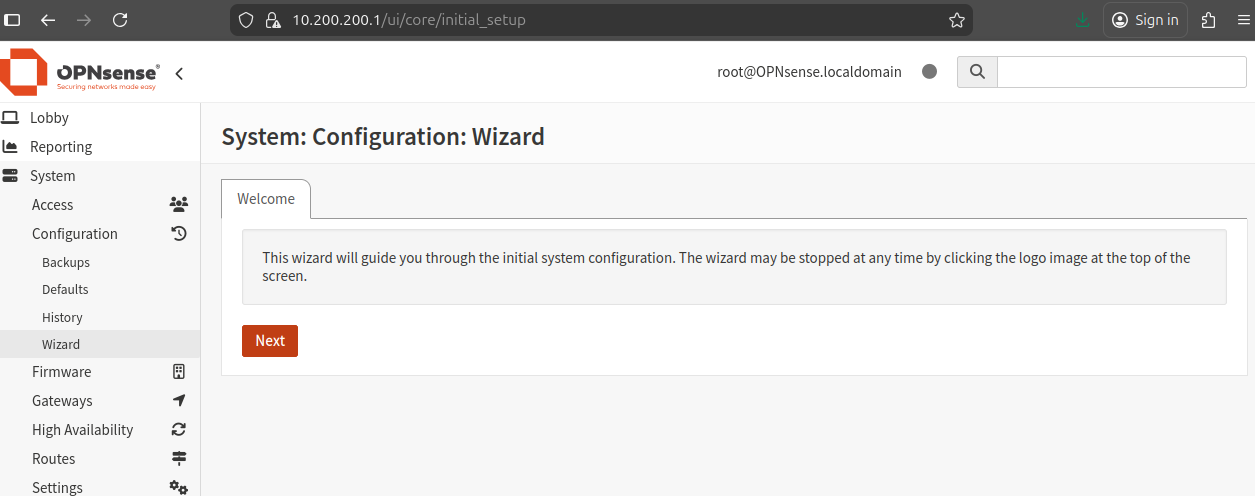
Click Next.
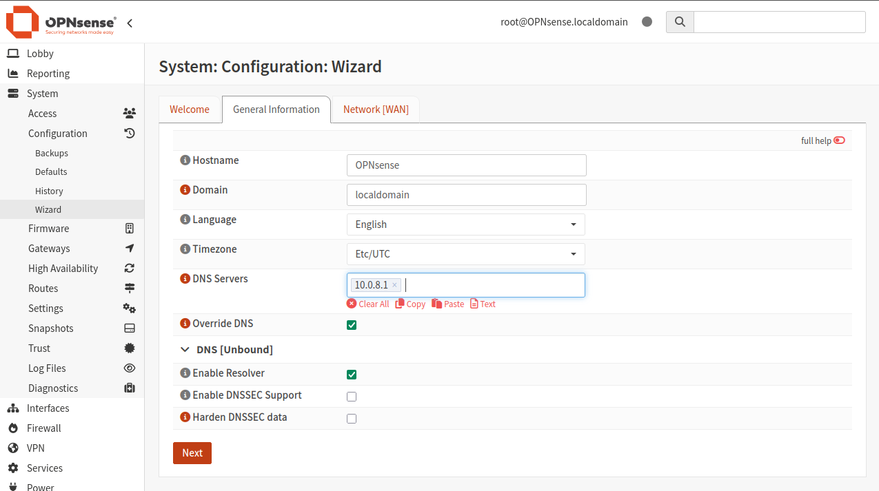
Set DNS Servers to 10.0.8.1 and click Next:
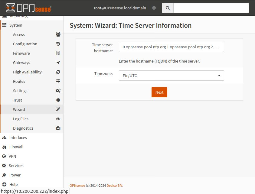
Set up time server information — just click Next to use the defaults:
The next screen is to configure the WAN interface:
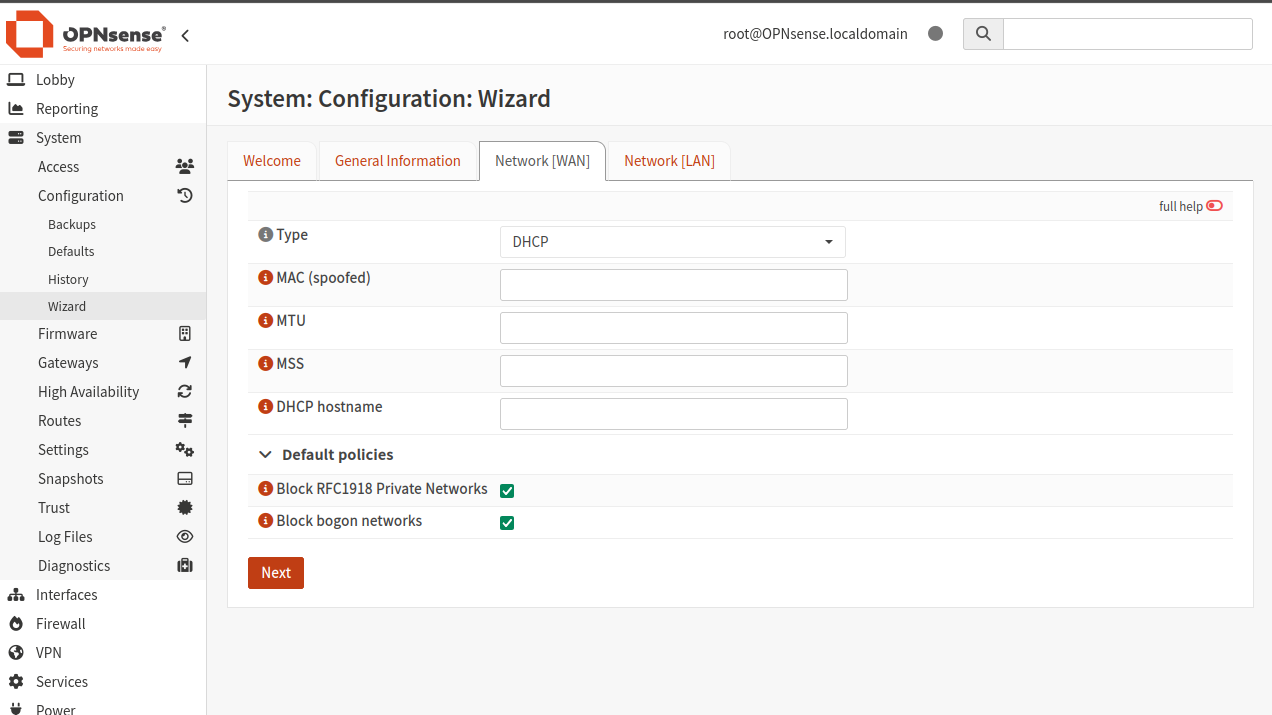
Click Next to use the defaults. The next screen is to configure the LAN interface:
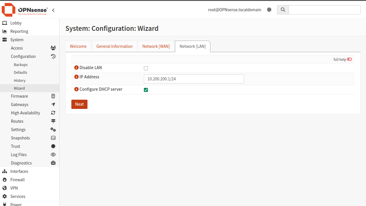
Enter the value of vtnet0, starting with 10.200.200.1 — your address will be similar, but different, so be careful!
Click Next to set the root password:
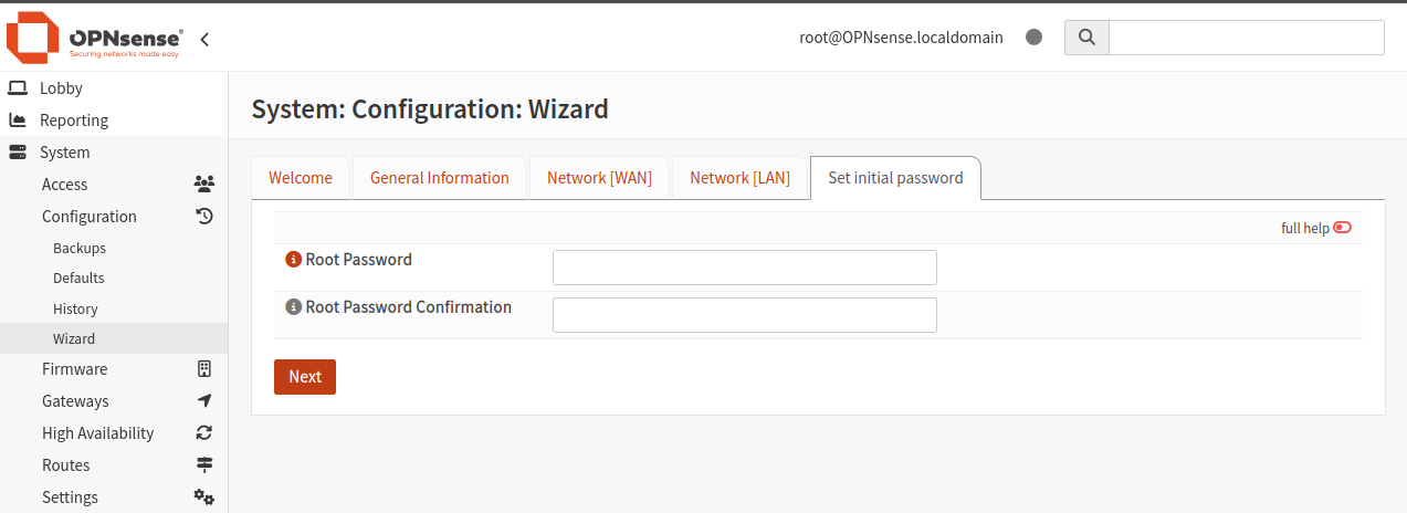
If you want to use the existing password, enter it in the confirmation field. If you’re going to use this server seriously, be sure to enter a new and robust root password here.
Once done, click Next and click Reload on the next screen to apply the changes:
Reloading may take a couple of minutes. Once finished, the wizard will redirect you to the dashboard.
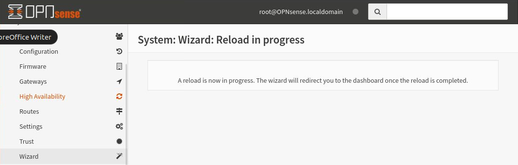
This is the final screen for the setup wizard:
Configure VPN service
Once the server has been set up, you can proceed with setting up the VPN service.
Create authority certificate
Click on System -> Trust -> Authorities to get a list of existing authorities:
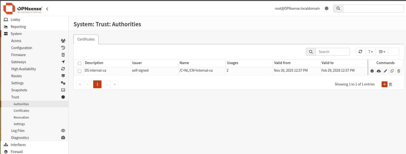
You can use any of the existing certificates, or click the plus button on the right to add a new one. Enter the following data:
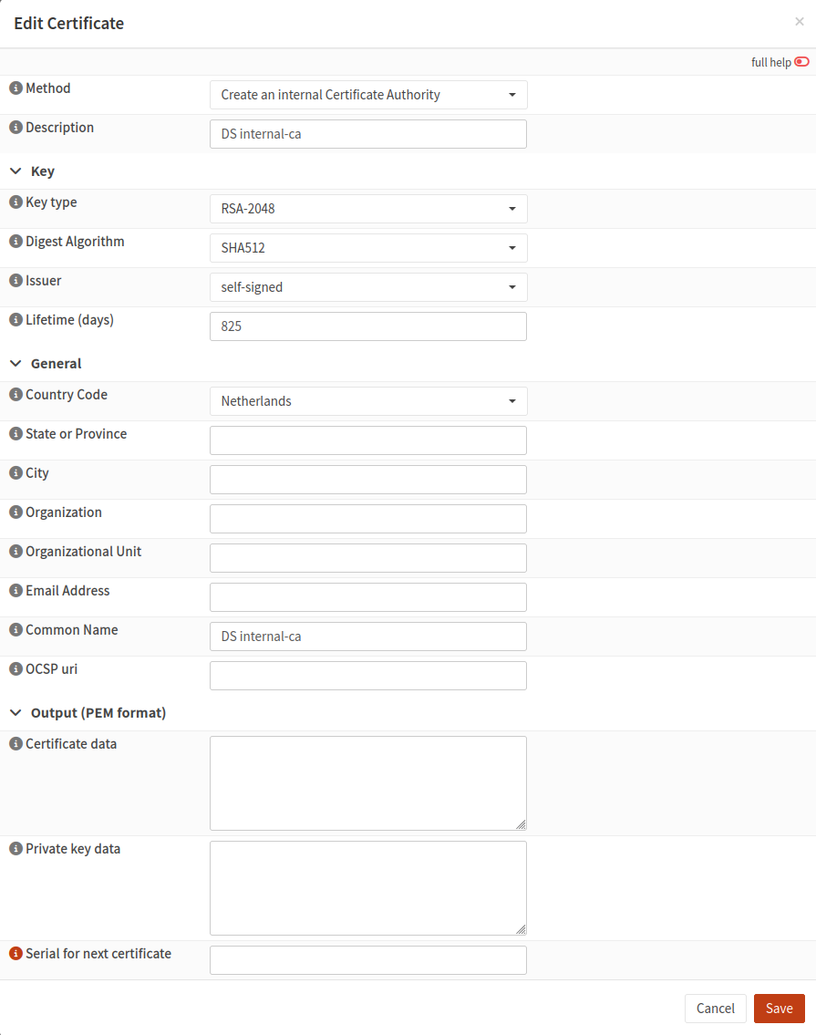
For Description, enter a meaningful certificate name, possibly with a random code like DS as a prefix (you can use your initials or any other prefix).
For Digest Algorithm, choose SHA512.
For Common Name, enter the same value as Description.
Other fields, such as country code, city, and organization, are not mandatory.
Click Save to save the entered data.
Add server certificate
Navigate to System -> Trust -> Certificates and click Add (scroll right if necessary to see it).
Click Add new CA to create a new certificate. Set the following values:
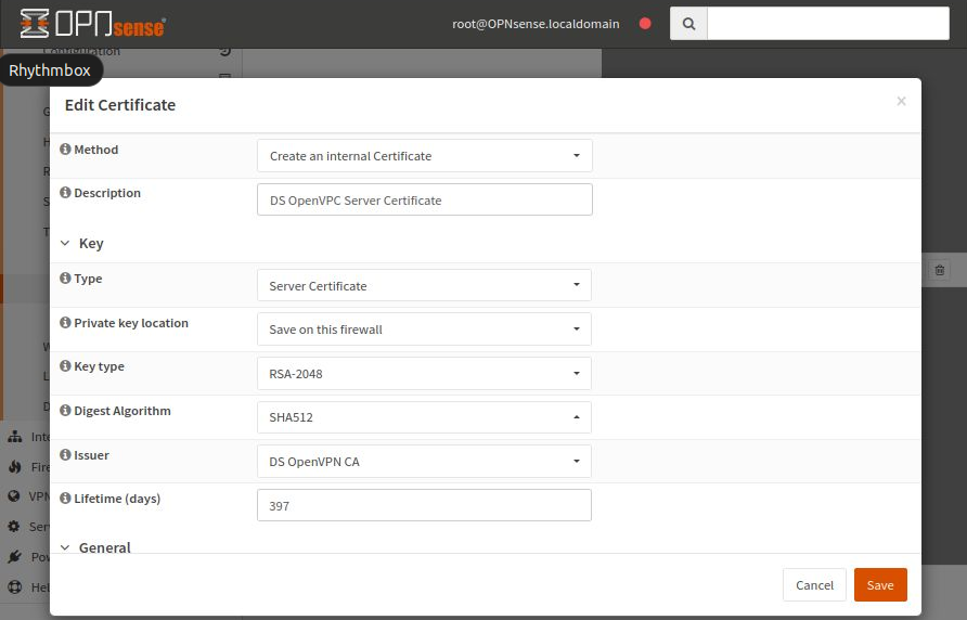
Enter internal-ca for Common Name. Other fields, such as country code and city, are not mandatory.
Click Save to save the entered data.
Create a user and add a user certificate
Navigate to System -> Access -> Users and ensure a user named root exists. You can create here new user (I have created user “test” earlier).
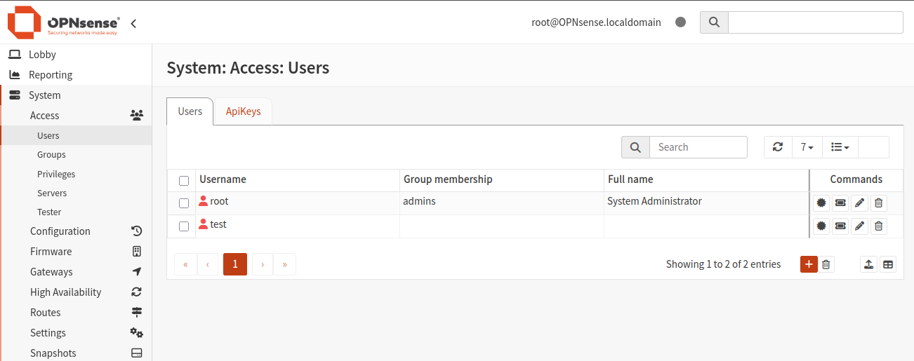
- New user should have privileges:
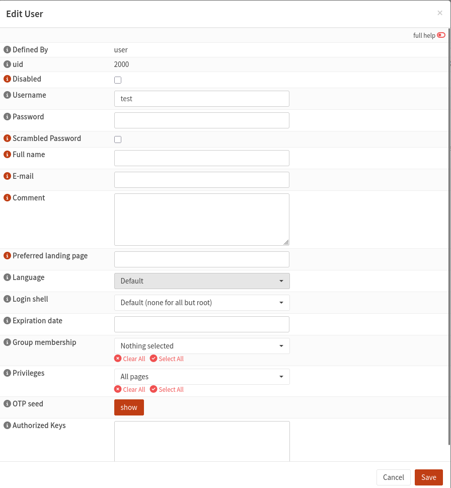
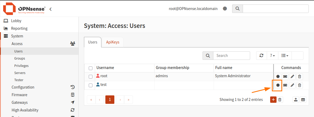
Click the icon “Search certificates by username” to the right of the window to edit it and add a certificate. Click Add.
Enter the data as shown in the image below:

The rest of the fields are not mandatory. Click Save to save the entered data.
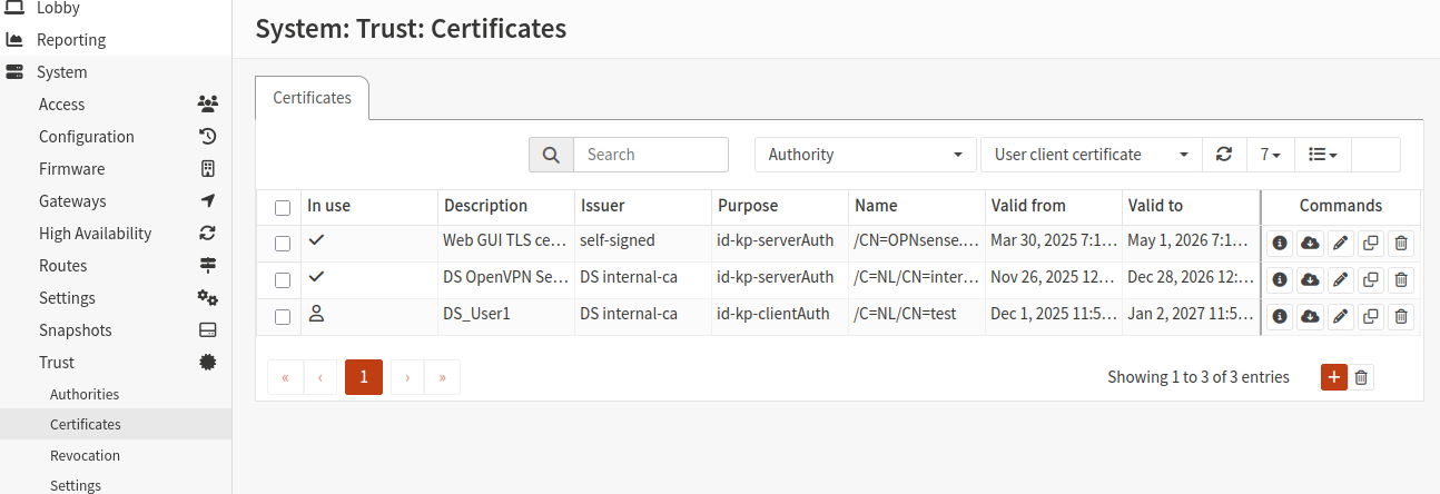
You should now see two new certificates in the list:
Create static key
To create a static key, navigate to VPN -> OpenVPN -> Instances -> Static Keys:
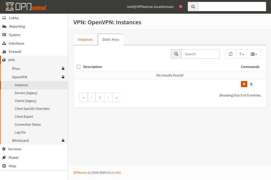
Select Add (plus sign icon) and start the process of creating a new static key.
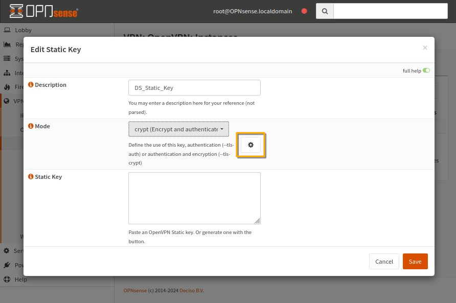
Enter a new name in the Description field and for Mode, choose crypt (Encrypt and authenticate…). To fill in the Static Key field, click the settings icon (orange rectangle in the image).
The Static Key will be generated and filled in automatically.
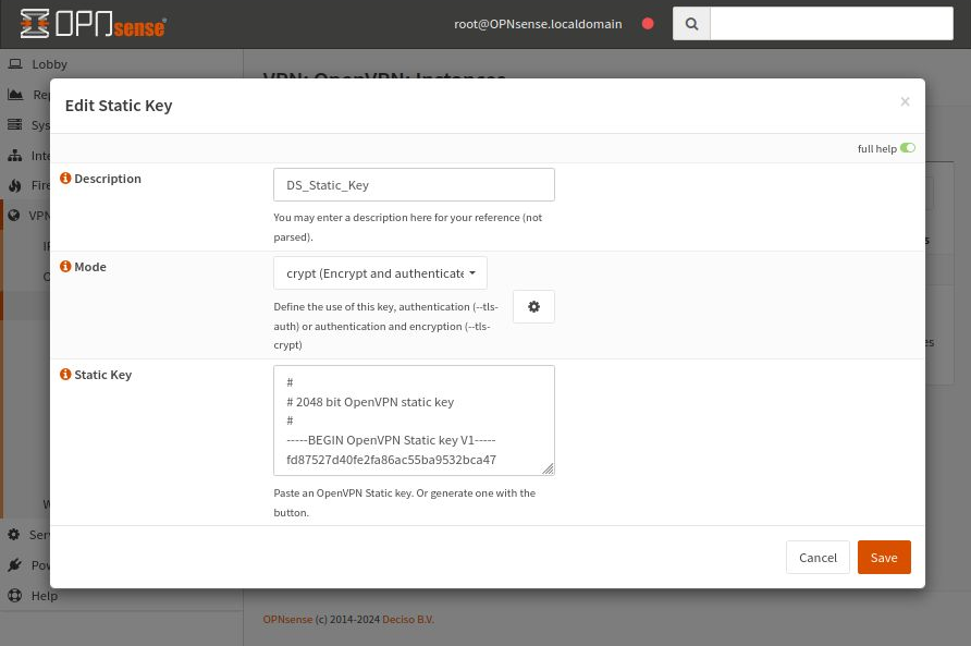
Click Save to save the entered data.
Create an OpenVPN Instance
Now that we have everything ready, let’s create a new OpenVPN instance on the OPNsense server.
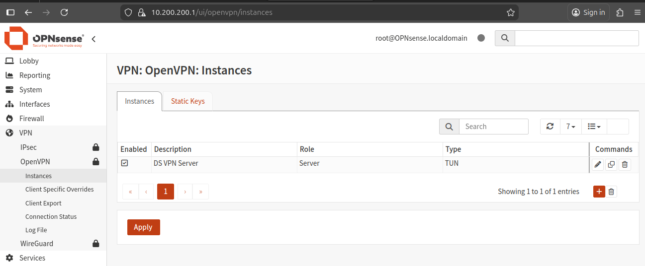
Navigate to the Instances tab under VPN -> OpenVPN -> Instances.
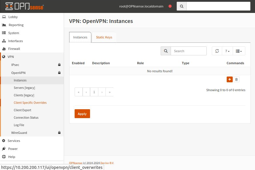
Click the orange plus button on the right.
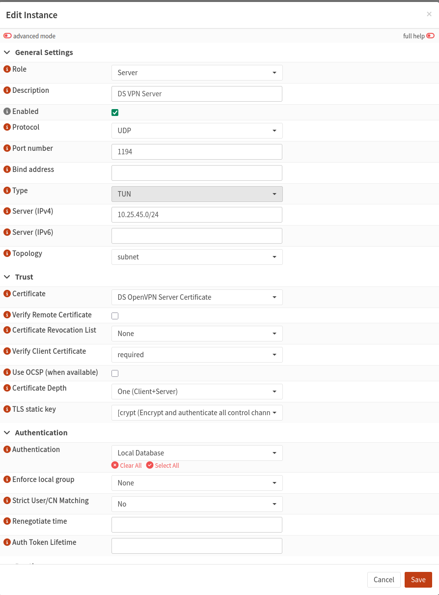
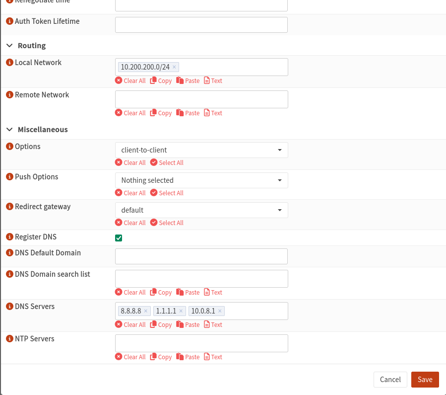
For the TLS static key, use the static key you created earlier (if available).
On the next screen, click Save, then click Apply. Without applying, the system will not accept the server configuration.
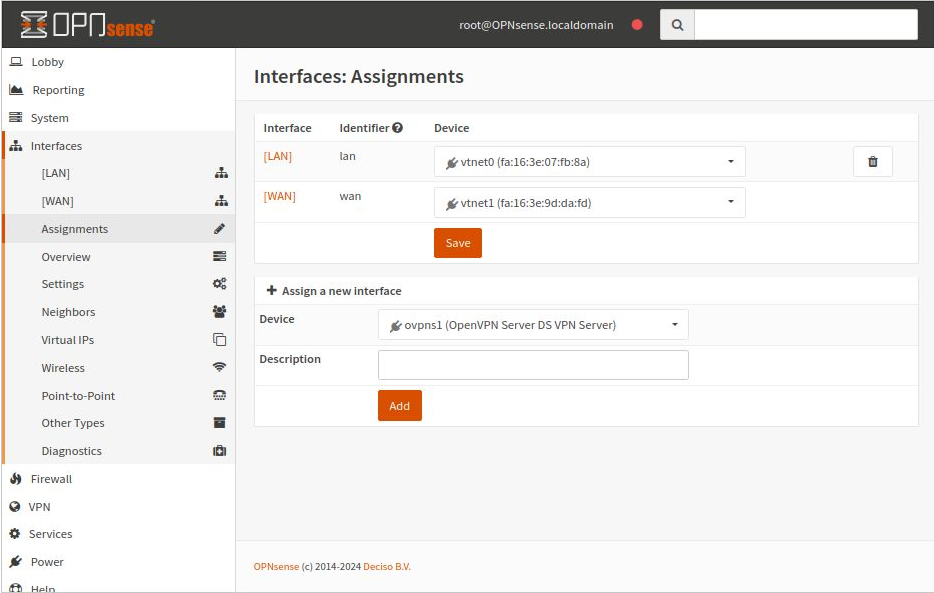
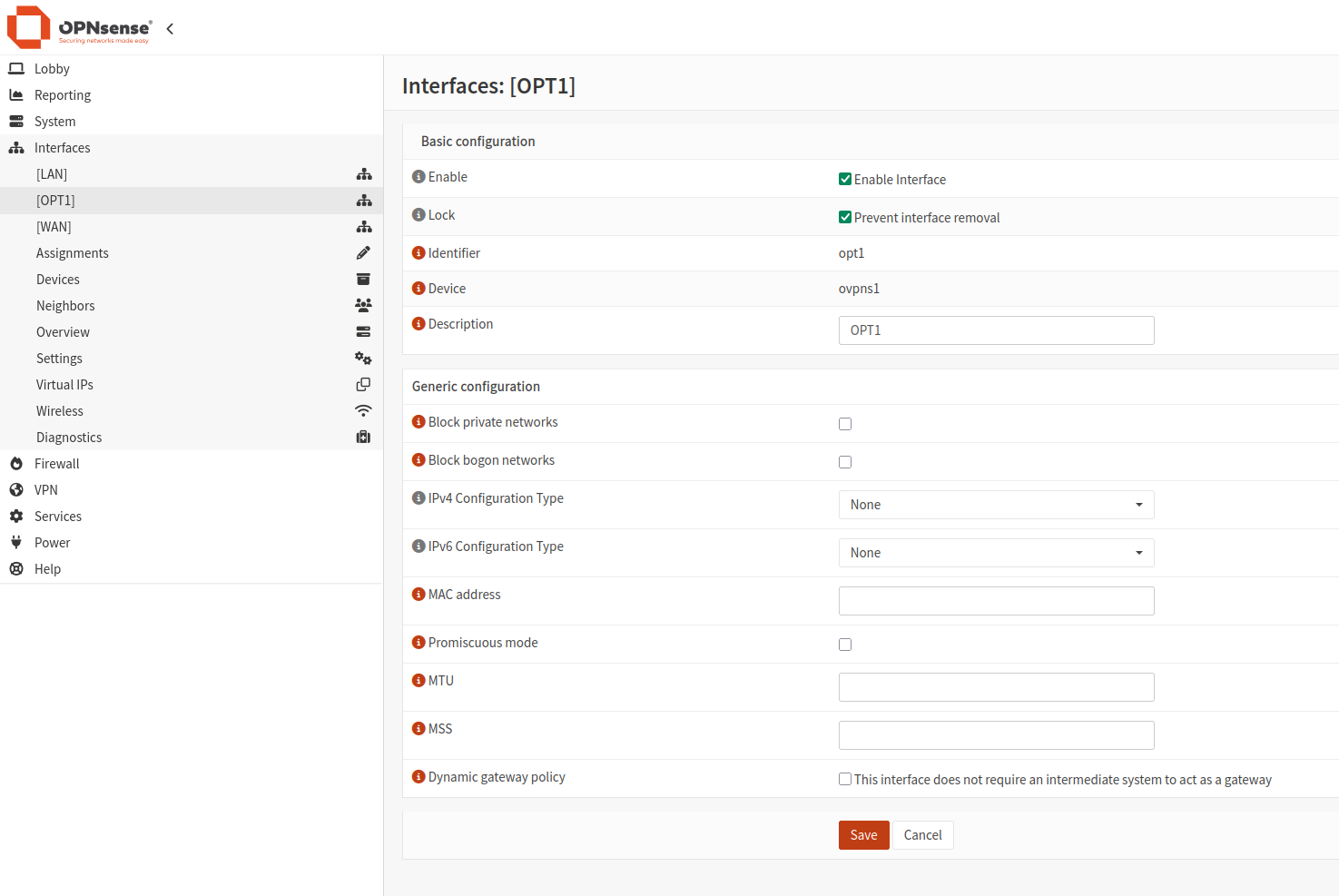
Assign an Interface to the OpenVPN Server
Next, assign an interface to the OpenVPN server.
Navigate to Interfaces -> Assignments.
Add a Rule to Connect to the OpenVPN Server
The first firewall rule allows clients to connect to the OpenVPN server.
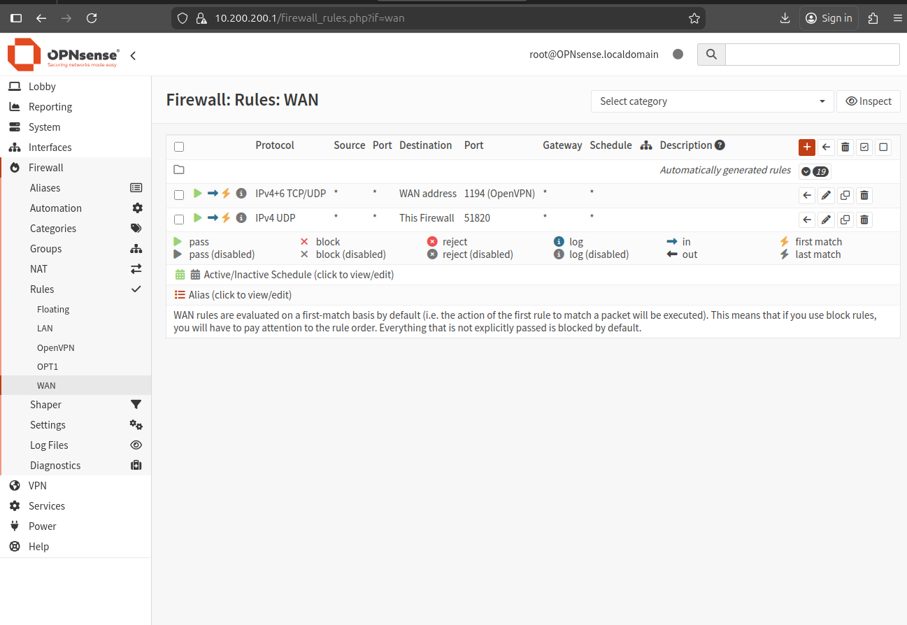
Go to Firewall -> Rules -> WAN and add a rule to allow traffic on the port selected when creating the OpenVPN instance.
After adding the rules, it will look like this:
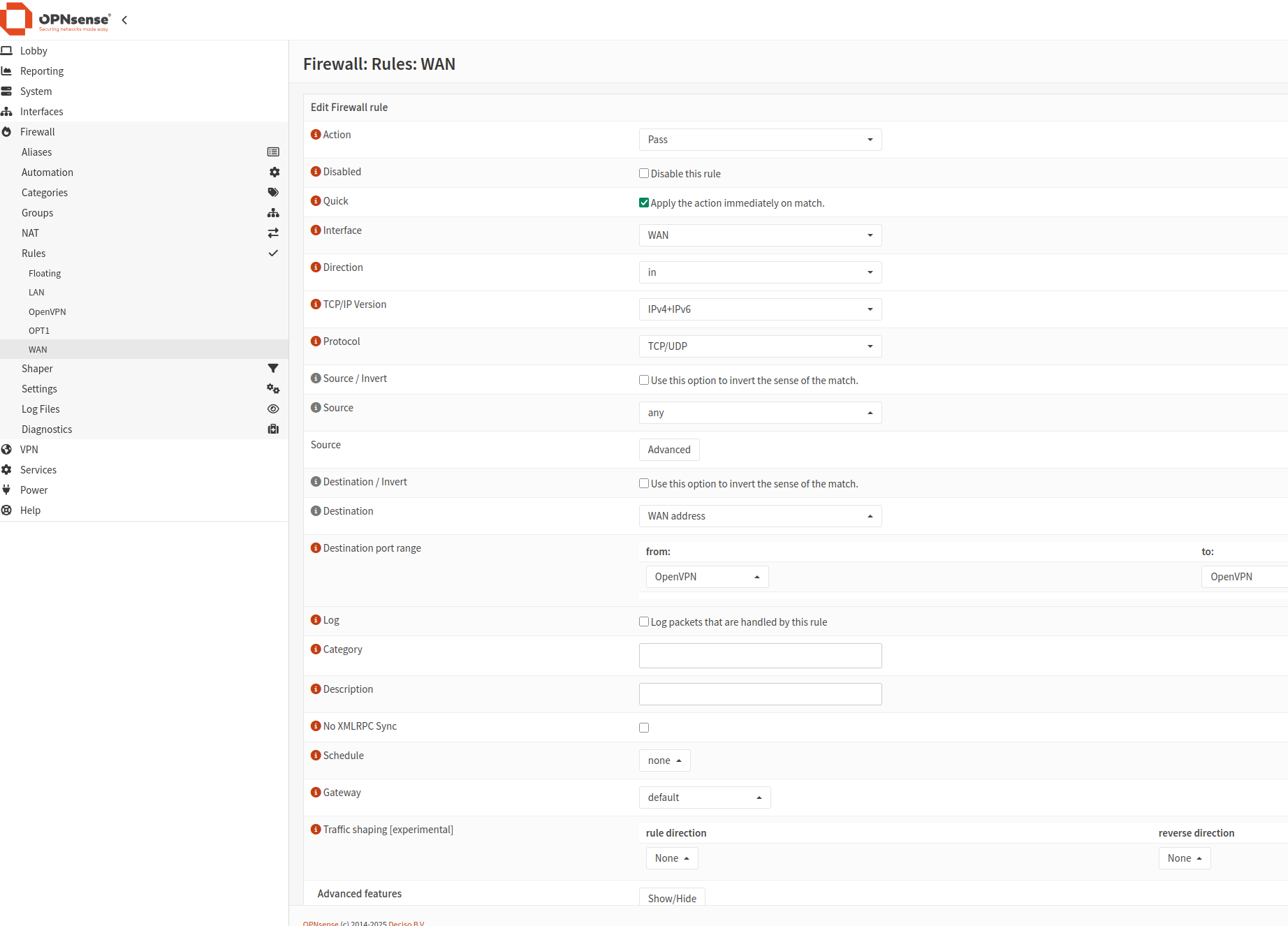
Click Add to create a new rule using the values shown in this images:
The first rule:
The second rule:
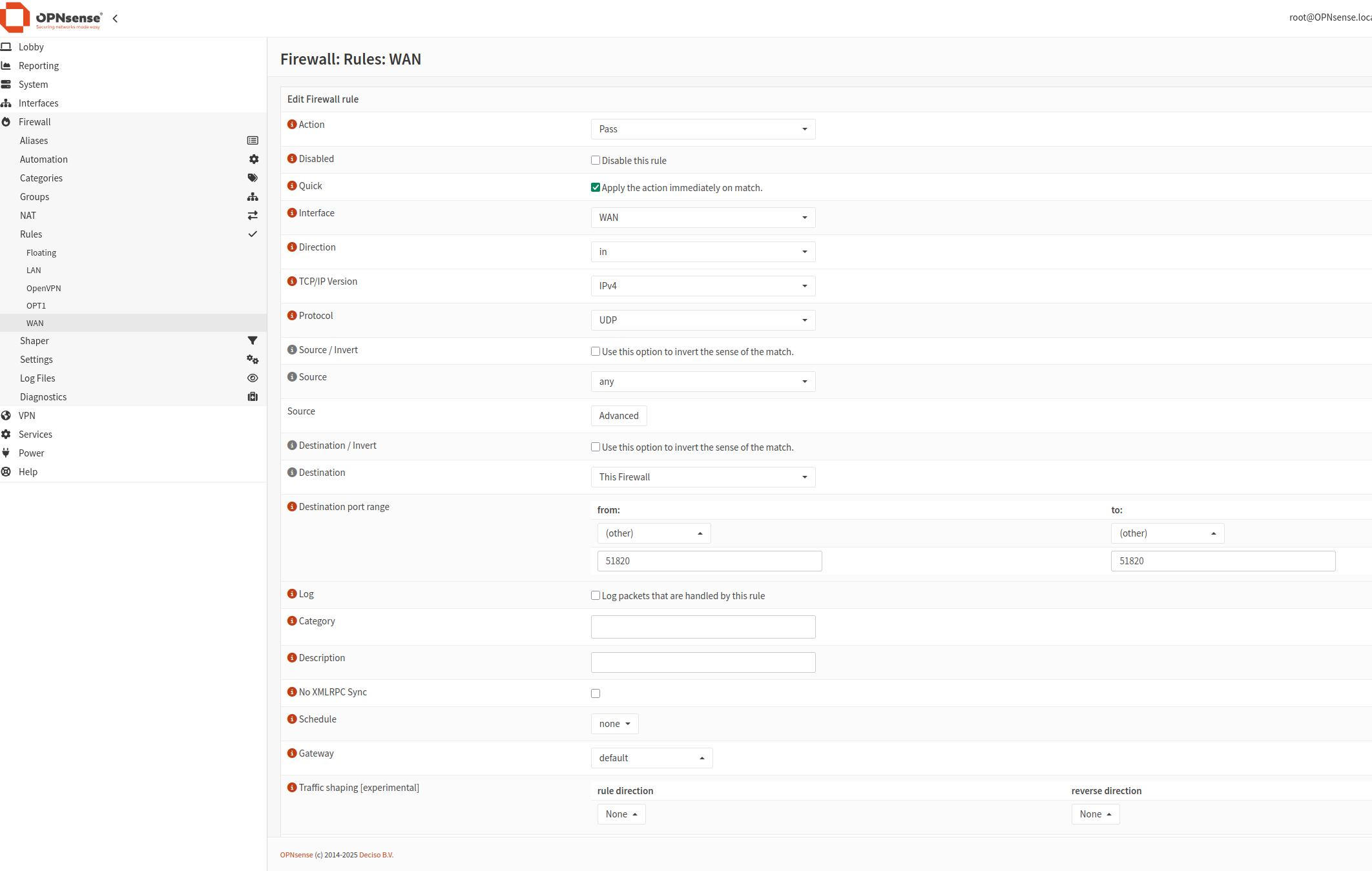
Click Save. The new rules will be applied once you click Apply changes.
Add a Rule to Allow Access to IPs
The second rule ensures that clients can access the intended IPs.
Navigate to Firewall -> Rules -> OPT1 (the interface you just created). For simplicity, we’ll add a rule to allow all traffic.
Click Add New to create a new rule.

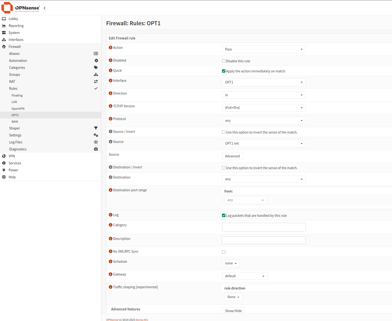
Once done, click Apply changes.
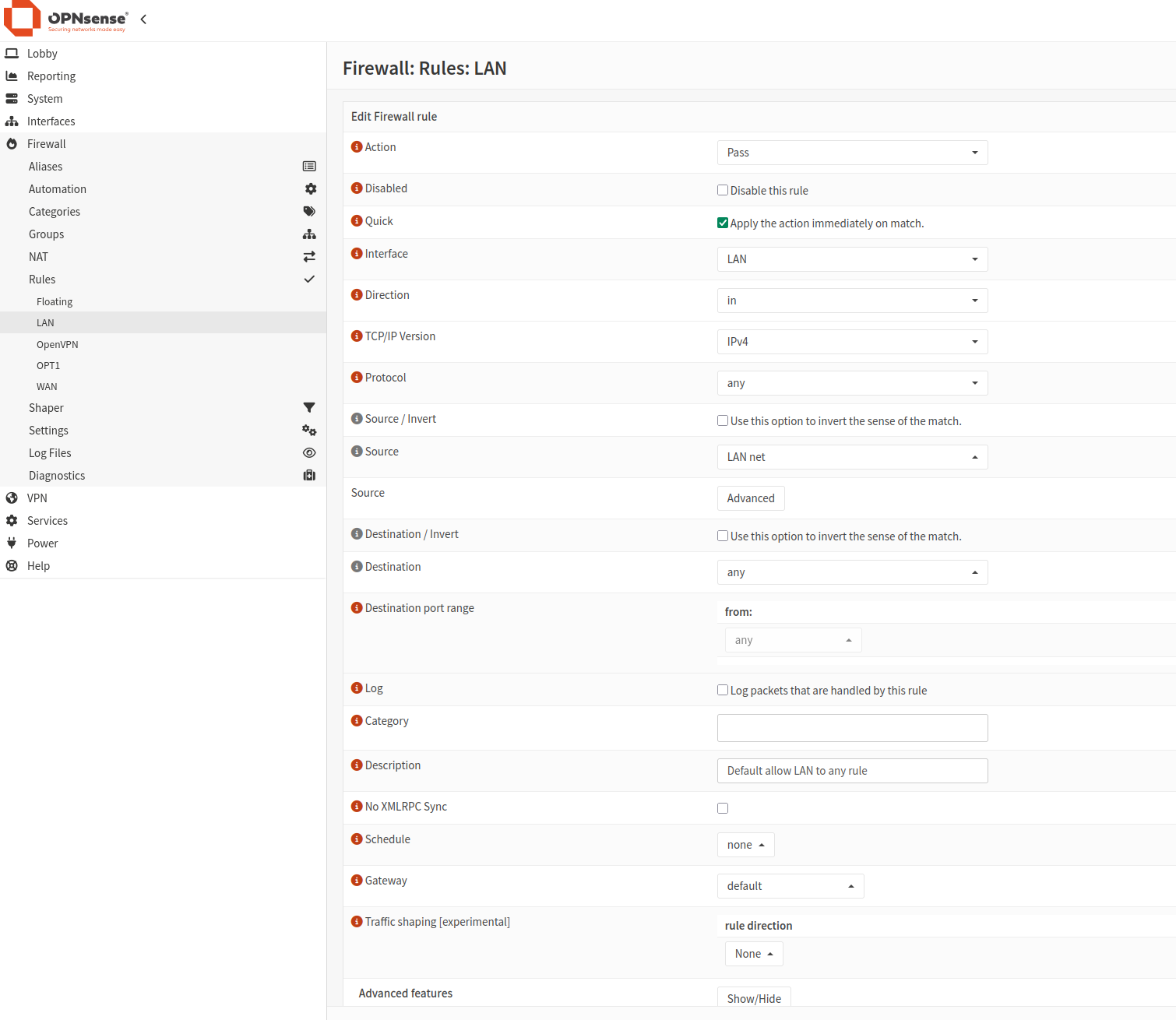
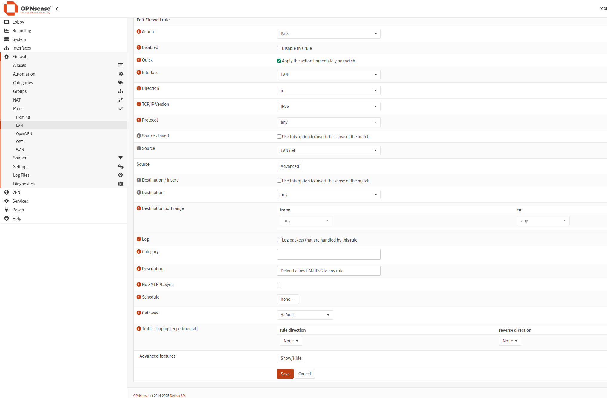
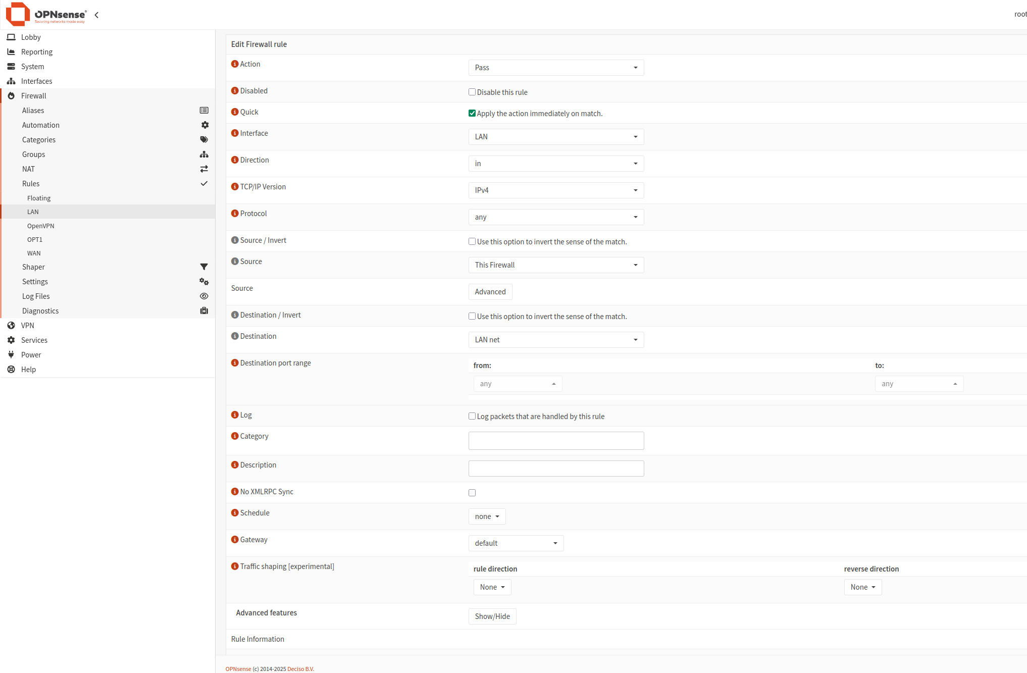
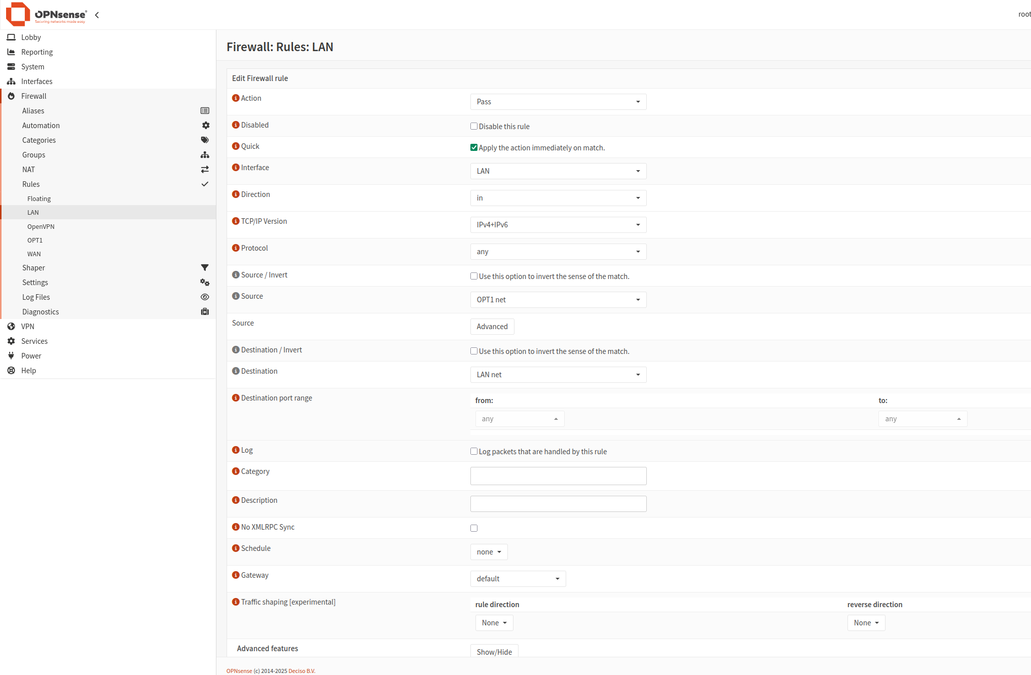
Add rules to LAN interface
The next step is to add rules to LAN interface. The result will look like this:
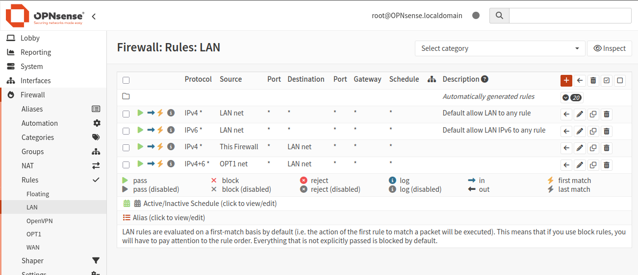
Click plus icon and add 4 rules:
Client Export
To export the client profile for remote access, follow these steps:
Remote Access Server: Select the server created in step 5.
Remote Access Server: Select the server created in Step 5.
Export Type: Select File Only.
Hostname: Enter the DDNS Fully Qualified Domain Name (FQDN) or Static Public IP Address of the server. Use the floating IP of Firewall_VM here.
Port: Use the port selected in Step 5.
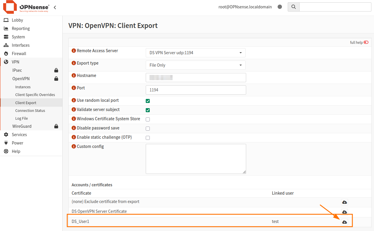
Click the cloud icon to download the Client Certificate for DS_User1.
The file will be downloaded.
Setting Up the OpenVPN Client
To connect to your VPN server, you’ll need a VPN client. You can use OpenVPN or Viscosity. Below are the instructions for setting up the OpenVPN client on different platforms.
### For Windows PCs:
Download and install the latest version of OpenVPN from [here](https://openvpn.net/community-downloads/).
Save all configuration files in C:/Program Files/OpenVPN/config and try to connect using the pre-configured credentials.
### For Linux (Ubuntu) PCs:
Open a terminal in the folder containing the configuration files.
Run the following commands:
sudo apt update
sudo nmcli connection import type openvpn file nameofyourovpnconffile.ovpn
You should see the output ‘Connection ‘nameofyourovpnconffile’successfully added.
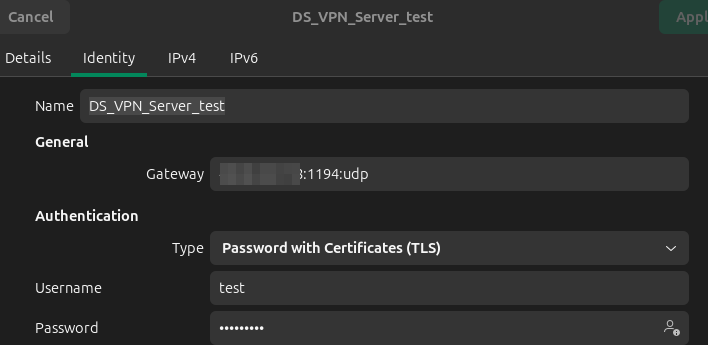
To connect, use the Ubuntu configuration bar (located at the top-right corner) and enter the appropriate credentials.
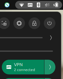
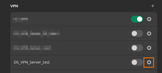
Enter credentials and connect:
If you don’t want to use the configuration bar, run this command:
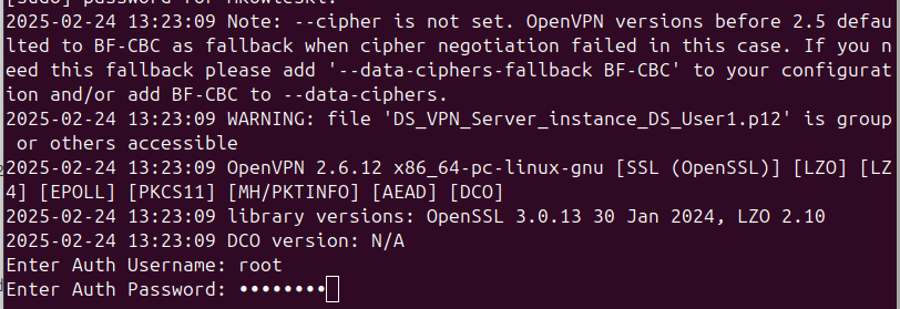
sudo openvpn --config nameofyourovpnconffile.ovpn
You will be prompted to enter the Auth Username and Auth Password. Use the credentials you created during the Create a user and add a user certificate step. If you didn’t create a new user, use the default:
Auth Username: root
Auth Password: opnsense
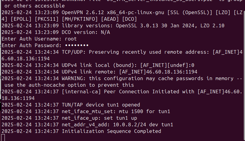
A successful connection should look like the following:
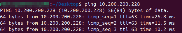
To test the VPN connection, open your local web browser and enter the internal IP address 10.200.200.1 You should be able to connect as shown below:
The next step is to navigate to Openstack dashboard and try to ping VM with Internal network attached. You can create new VM.
In this example:

Testing ping from your local machine with VPN enabled: